Description
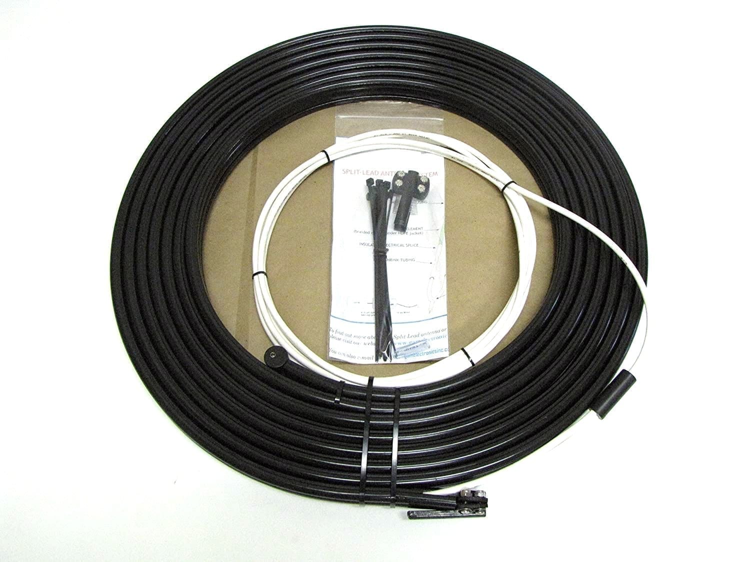
The GAM/McKim Split Lead Single Side Band Antenna is a favorite amongst sail boaters because it eliminates the need for backstay insulators forever. The Split Lead antenna simply press fits onto your existing backstay wire with no special tools or equipment required. The GAM/McKim is secured at the base by a hard grade plastic T clamp and requires a back stay length of at least 34 feet.
Safety
The split lead antenna installation requires no alteration of the backstay thus preserving full mechanical integrity of the backstay wire. All RF elements of the antenna are fully insulated eliminating the possibility of the shock hazard posed by the bare wire connection in conventional backstay antennas.
Ease of Installation
No cutting, no swaging, no measuring, no special tools, no special skills required. Simply press fit the GAM/McKim over the existing backstay wire, clamp at bottom and secure in place with included Zip-Ties. Click here for installation instructions.
Performance
Active elements are designed for RF, meaning they are more conductive than the stainless steel backstay wire. Lead wire connections are waterproof and electrically sound. The antenna’s insulated housing reduces precipitation static, often associated with heavy squalls and thunderstorms.
Stowage and Portability
The Split Lead antenna can be coiled up to a diameter of approximately 26” for ease of storage. It can be easily removed when the mast or backstay require work and can readily be transferred from one vessel to another.
Durability
The outer housing is very durable, resistant to weathering and, since it is under no mechanical stress, should last for many years in the marine environment.
Cost
The GAM/McKim Split Lead Antenna is priced to compete with conventional backstay insulators (including swaging costs) and less expensive than many insulators utilizing reusable terminals.
Click here for installation instructions.
Installation Instruction
GENERAL: The GAM/McKim Split Lead Antenna is designed for Single Side Band Marine Radios with Tuners. You will need 34 feet of space on your backstay. The backstay diameter should be between ¼” and 7/16”. As the name implies, the center tube of the antenna housing is split which allows it to be put onto the backstay slid up the stay until you have reached the height that you desire for the bottom of the antenna housing. The antenna is supplied with 15 feet of GTO-15 for connection to the tuner.
Step 1. Starting with the end of the antenna opposite the GTO-15 wire, open the split in the center tube and start feeding the housing onto the backstay cable. Once started it should be relatively easy to slide the entire antenna up the backstay. It is suggested that the split be facing away from the mast. You may use the black nylon wire ties provided with the antenna at 4 foot intervals if you are concerned with the ability of the housing to stay in place. The wire ties, if used, should be tightened lightly so as to stay in place on the housing without restricting the movement of the tube on the backstay.
Step 2. If the backstay diameter is 5/16” proceed to step 3. For 3/8” or 7/16” backstays tighten the screws on the clamp being sure the clamping fingers remain aligned. Then drill out the clamp to the proper size for your backstay. For 3/8” backstay use a 23/64” drill; For 7/16” use a 27/64” drill. We recommend using a drill press and a drill vice to hold the clamp and align the hole. Be sure to use proper drilling techniques and use eye protection when drilling.
If your backstay is ¼” diameter drill the clamp as if for 3/8” and use the small plastic tube that has been slit over the backstay before installing the clamp over the plastic tube. This tube will take up the space and insure proper fit and hold of the clamp. You may also choose to use similar plastic tubing (available at most hardware/building supply stores) under each nylon wire tie to prevent rattling of the antenna housing.
Step 3. Once you are satisfied with the placement of the antenna housing install the clamp with the fingers over the center tube using the four screws, washers and self-locking nuts supplied. The GTO-15 wire should be bent down into the relief slots in the outer tubes to allow the clamp fingers to engage the center tube. It is recommended that the head of the screw be on the same side as the wire relief to reduce the possibility of abrasion of the GTO-15 connector wire. Do not over tighten the clamp screws.
Step 4. Proceed with the connection of the GTO-15 wire to the tuner.
Notes: Since the active antenna elements are fully contained within the non-conductive housing there is no requirement to have the antenna out of reach of the people on deck. Good radio practices and procedures should be followed.
Any questions or comments should be directed to: GAM Electronics; P.O. Box 305 Harrison, ME 04040. 1-207-583-4670